
Engineering
Physics
Semiconductors
Question
Draw the circuit diagram of AND gate using diodes.
Know your College Admission Chances Based on your Rank/Percentile, Category and Home State.
Get your JEE Main Personalised Report with Top Predicted Colleges in JoSA
Solution

AND gate: An AND gate has two or more inputs but only one output. It is known as AND gate because the output is high only when all the inputs are high. The logic symbol of a two input AND gate is shown in Figure(a).
AND gate may be thought of an electrical circuit as shown in Figure (b), in which the switches are connected in series. Only if A and B are closed, the lamp will glow, and the output is high.
Diode AND gate;
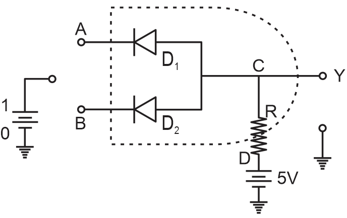
Figure shows a simple circuit using diodes to build to a two-input AND gate. The working of the circuit can be explained as follows.
Case(i) A = 0 and B = 0.
When A and B are zero, both diodes are in forward bias condition and they conduct and hence the output will be zero, because the supply voltage VCC will be dropped across RL only. Therefore Y = 0.
Case(ii) A = 0 and B = 1.
When A = 0 and B is high, diode D1 is forward biased and diode D2 is reverse biased. The diode D1 will now conduct due to forward biasing. Therefore, output Y = 0.
Case(iii) A = 1 and B = 0.
In this case, diode D2 will be conducting and hence the output Y = 0.
Case(iv) A = 1 and B = 1.
In this case, both the diodes are not conducting. Since D1 and D2 are in OFF condition, no current flows through RL. The output is equal to the supply voltage. Therefore Y = 1.
Thus the output will be high only when the inputs A and B are high. The Table summaries the function of an AND gate.
Please subscribe our Youtube channel to unlock this solution.