Engineering
Physics
Logic Gates New
Question
What do you understand by the logic gate? Draw the symbol for XOR gate and also the truth table.
Know your College Admission Chances Based on your Rank/Percentile, Category and Home State.
Get your JEE Main Personalised Report with Top Predicted Colleges in JoSA
Solution

A logic gate is an elementary building block of a digital circuit. Most logic gates have two inputs and one output. A logic gate is a digital circuit that follows the certain logical relationship between the input and output voltages. The five common logic gates used are OR gate, AND gate, NOT gate, NOR gate, and NAND gate.
Each logic gate is indicated by a symbol and its function is defined by a truth table that shows all the possible input logic level combinations with their respective output logic levels. Truth tables help to understand the behaviour of logic gates. These logic gates can be realized using semiconductor devices.
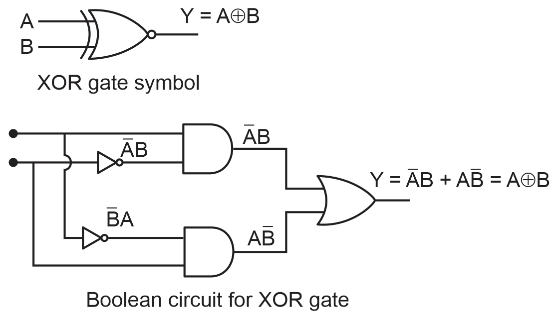
The Boolean expression for XOR gate is:
Y = A ⊕ B
When any one of the input signals A or B has value 1 then only Y = 1. If the two inputs are 0 or 1 then output is 0. Hence, the truth table for this gate is:
| A | B | Y = A ⊕ B |
| 0 | 0 | 0 |
| 0 | 1 | 1 |
| 1 | 0 | 1 |
| 1 | 1 | 0 |
The XOR gate symbol is shown in the figure. The truth table for the expression;
| A | B | |||||
| 0 | 0 | 1 | 1 | 0 | 0 | 0 |
| 1 | 0 | 0 | 1 | 1 | 0 | 1 |
| 0 | 1 | 1 | 0 | 0 | 1 | 1 |
| 1 | 1 | 0 | 0 | 0 | 0 | 0 |
Hence, by using Boolean expression gate can be constructed. This is shown in the figure in which we have used AND, OR and NOT gates.